Experiment
Settings
We evaluate our PED method, both the global path-encoding-based strategy, PEDG, and decomposed path-encoding-based strategy, PEDD, on various compositional hybrid systems, all involving discontinuous behavior that cannot be solved by gradient-based methods. Our approach is implemented in Java and all the experiments are conducted on the same PC (Intel Core i7 2.30GHz, 32GB RAM, Windows 10).
Our approach is evaluated on three different systems, the robotic arm systems(marked as Arm), quadcopter drone systems (marked as Drone), and three different vehicle systems, with respect to different scenarios of the straight road (Veh-a), crossroad (Veh-b), and T-junction (Veh-c).
File description
In models, we have 30 files and can be divided into two categories, xml files and cfg files. xml files describe the automata of systems, and cfg files detail the following infomation:
- system: the name of system
- initially: the initial parameters value or range
- target_x: the target position in X axis
- target_y: the target position in Y axis
- (Optional) target_z : the target position in Z axis
- obj_function: the objective function
For example, Drone.xml gives the automaton of a quadcopter drone system and Drone-2.cfg gives the information of the second component in drone system.
For each scenario, we set the number of components in the system as 1, 2, 3 and 5 respectively. For example, Arm-2 stands for the robotic arm system with first two components, Arm-1.cfg and Arm-2.cfg , while Drone-5 stands for the system with all five drones.
Results
| Success rate (%) | Time cost (s) | Memory cost (MB) | Simulation rounds | Optimization value | |||||||||
|---|---|---|---|---|---|---|---|---|---|---|---|---|---|
| Benchmark | CDH | PEDG | PEDD | CDH | PEDG | PEDD | PEDG | PEDD | PEDG | PEDD | CDH | PEDG | PEDD |
| Arm-1 | 100 | 100 | 100 | 41.20 | 12.89 | 8.25 | 371.55 | 247.44 | 819.53 | 420.12 | -9999.1 | -9997.4 | -9996.3 |
| Arm-2 | 0 | 100 | 100 | N/A | 79.41 | 41.70 | 389.64 | 313.22 | 15315.36 | 15761.64 | N/A | -19991.2 | -19989.6 |
| Arm-3 | 0 | 100 | 100 | N/A | 183.22 | 80.89 | 414.21 | 396.15 | 26747.39 | 16392.65 | N/A | -29977.2 | -29990.9 |
| Arm-5 | 0 | 100 | 100 | N/A | 891.77 | 90.21 | 679.36 | 453.68 | 35479.47 | 19203.20 | N/A | -49985.6 | -49989.6 |
| Veh-a-1 | 100 | 100 | 100 | 80.45 | 10.41 | 9.82 | 210.29 | 187.84 | 271.91 | 82.39 | -9995.6 | -9989.2 | -9993.7 |
| Veh-a-2 | 100 | 99 | 100 | 1913.24 | 69.73 | 45.25 | 256.91 | 258.45 | 2297.60 | 1657.12 | -19993.5 | -19991.2 | -19995.4 |
| Veh-a-3 | 19 | 94 | 96 | 3406.64 | 334.64 | 234.46 | 268.02 | 222.69 | 5695.50 | 2761.90 | -29985.2 | -29969.3 | -29979.5 |
| Veh-a-5 | 0 | 62 | 74 | N/A | 2611.57 | 1885.80 | 273.65 | 236.07 | 11288.70 | 7218.55 | N/A | -49936.5 | -49983.7 |
| Veh-b-1 | 100 | 100 | 100 | 8.31 | 4.24 | 3.98 | 210.11 | 183.53 | 102.38 | 97.29 | -9994.2 | -9997.3 | -9995.3 |
| Veh-b-2 | 100 | 100 | 100 | 1502.40 | 78.52 | 41.14 | 249.25 | 212.44 | 3814.20 | 1934.38 | -19999.2 | -19998.3 | -19996.8 |
| Veh-b-3 | 53 | 89 | 96 | 2961.63 | 417.35 | 217.18 | 259.43 | 192.26 | 8614.70 | 3276.20 | -29990.8 | -29984.1 | -29981.4 |
| Veh-b-5 | 0 | 61 | 91 | N/A | 2478.92 | 538.47 | 276.80 | 210.46 | 14201.40 | 4010.20 | N/A | -49985.2 | -49990.4 |
| Veh-c-1 | 100 | 100 | 100 | 33.76 | 6.18 | 5.28 | 264.36 | 193.21 | 593.63 | 128.09 | -9998.4 | -9999.4 | -9996.8 |
| Veh-c-2 | 100 | 100 | 100 | 1834.68 | 50.43 | 30.08 | 243.98 | 228.95 | 2189.30 | 1870.00 | -19996.1 | -19992.2 | -19987.8 |
| Veh-c-3 | 45 | 95 | 99 | 3519.77 | 357.52 | 121.15 | 278.30 | 235.30 | 7287.00 | 2715.03 | -29983.6 | -29979.1 | -29987.3 |
| Veh-c-5 | 0 | 76 | 83 | N/A | 1127.56 | 360.48 | 321.60 | 286.70 | 21360.00 | 8184.27 | N/A | -49991.2 | -49984.4 |
| Drone-1 | 100 | 100 | 100 | 14.69 | 8.47 | 7.46 | 367.87 | 241.64 | 593.10 | 391.20 | -9988.5 | -9978.5 | -9985.9 |
| Drone-2 | 0 | 59 | 63 | N/A | 2102.96 | 1354.52 | 379.33 | 251.45 | 8568.40 | 5566.00 | N/A | -19894.4 | -19976.6 |
| Drone-3 | 0 | 24 | 35 | N/A | 2914.45 | 2400.53 | 492.14 | 287.73 | 28293.22 | 19462.34 | N/A | -29994.7 | -29985.1 |
| Drone-5 | 0 | 18 | 27 | N/A | 3497.25 | 2695.32 | 653.21 | 325.66 | 35821.00 | 23715.00 | N/A | -49892.1 | -49940.3 |
Video result on robotic arm testbed
To verify the feasibility of our methods, we upload the optimal control results generated by PED for Arm-2 system and set up a collision-occurred scenario. The overall view of our test bed is shown in the following figure.
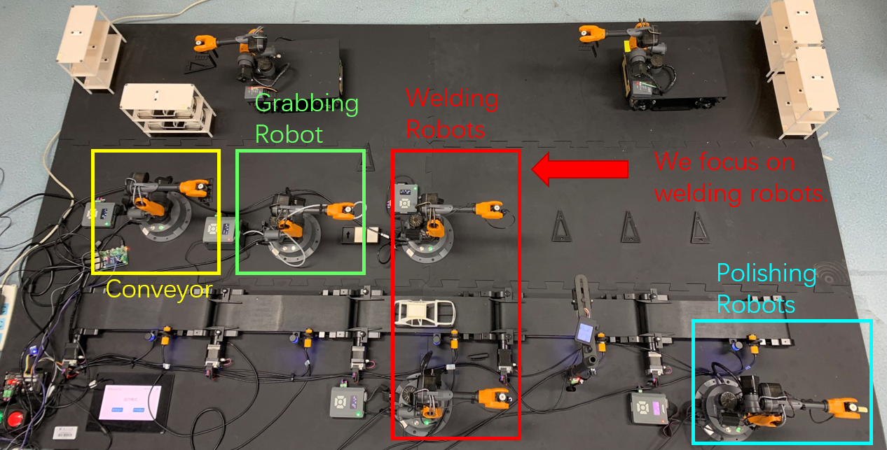
The entire car welding roof assembly line includes 5 fixed robots, 2 mobile robots, and several conveyor belts. Firstly, the robotic arm in the yellow box transports the roofless body from the shelf to the conveyor belt; Next, the conveyor belt transports the car body forward, and the arm in the green box places the roof onto the car body; Next, the robotic arm in the red box will weld the roof; Finally, it will be sent to robotic arm in the blue box for polishing.
For experiment, we focus on two welding robots, respectively Arm 1 and Arm 2 in the following figure.
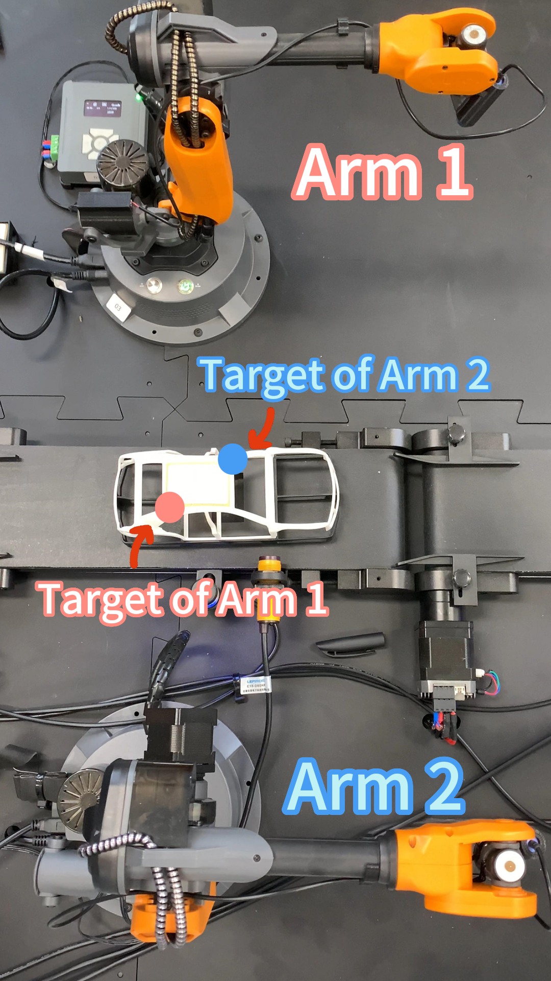
We envision a scenario where the welding target point of robotic arm 1 is at the red dot, and robotic arm 2 is at the blue dot. We upload the optimal control results generated by PED for the scenario and record the videos respectively with usual control and PED results as following.
| Collision occurs with usual control. | PED generates collision-free results. | |
|---|---|---|
| Video | ||
| Gif |  |
 |